Acropolis Family Hardware Overview

Acropolis Family Design Blocks
Design blocks are a built-in feature of the EAGLE CAD where users can design small self-contained circuits that are intended to be reused in multiple projects. Design blocks consist of a schematic, a corresponding PCB layout, and optional technical implementation notes. The Acropolis family hardware leverages AutoCAD, EAGLE's design block feature by ensuring reusable hardware systems are abstracted from species into design blocks that are added to an open-source git repository. This system reduces development time and the occurrence of layout mistakes and errors for Acropolis PCBs.
When using this system, the process of designing a new Acropolis PCB begins by selecting the design blocks which provide the new artefact's desired functionality (e.g. LED feedback, audio sensing, ambient light sensing). The relevant design blocks are imported into the species project. The implementation notes for each design block should be read while any unneeded components should be removed from the project. The remaining components should then be electronically connected in the schematic before being placed and connected within the board view. Before introducing high-level guidelines for the Acropolis family hardware implementation, the remainder of this discussion covers each of the Acropolis family design blocks.
Micrcontroller Design Block
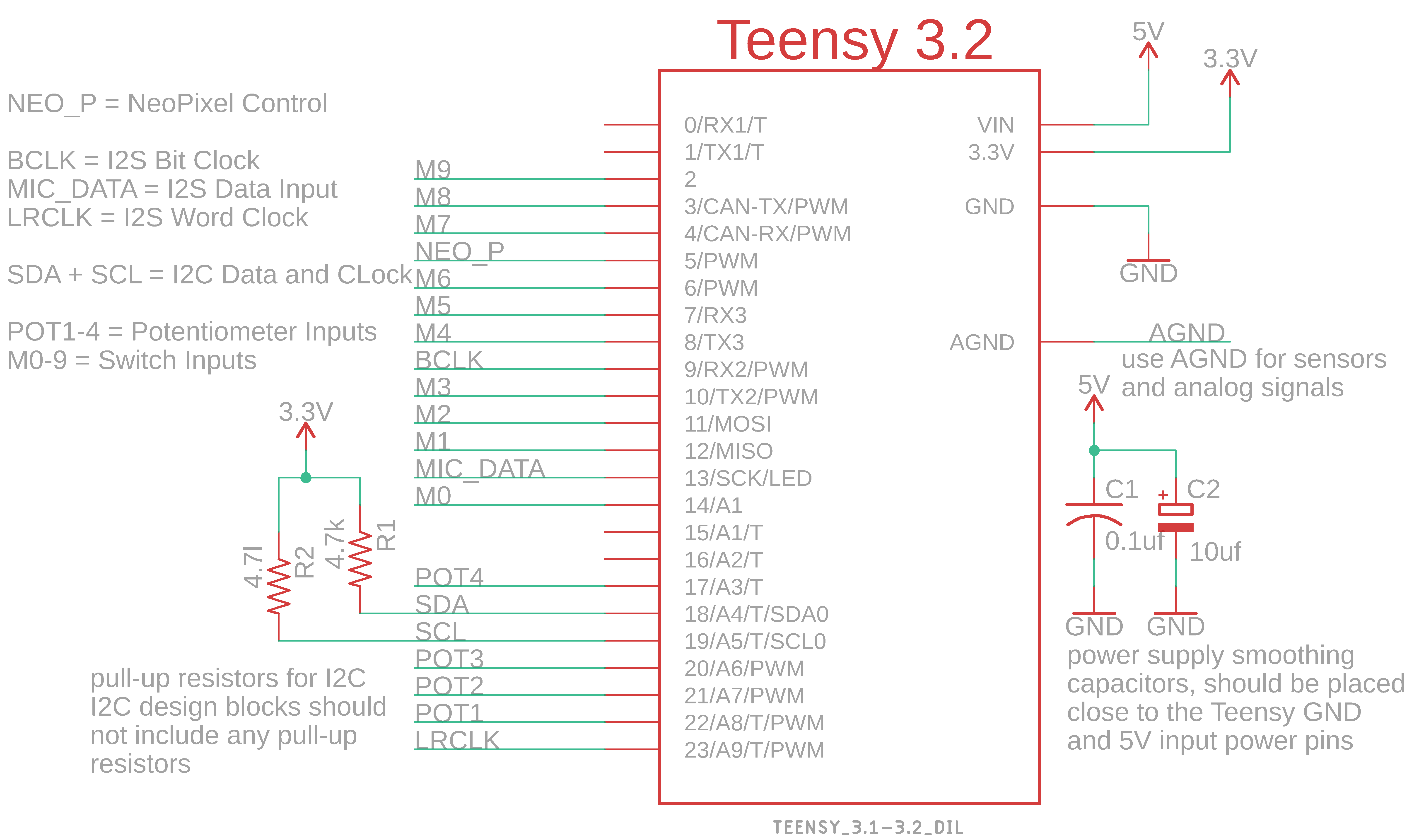
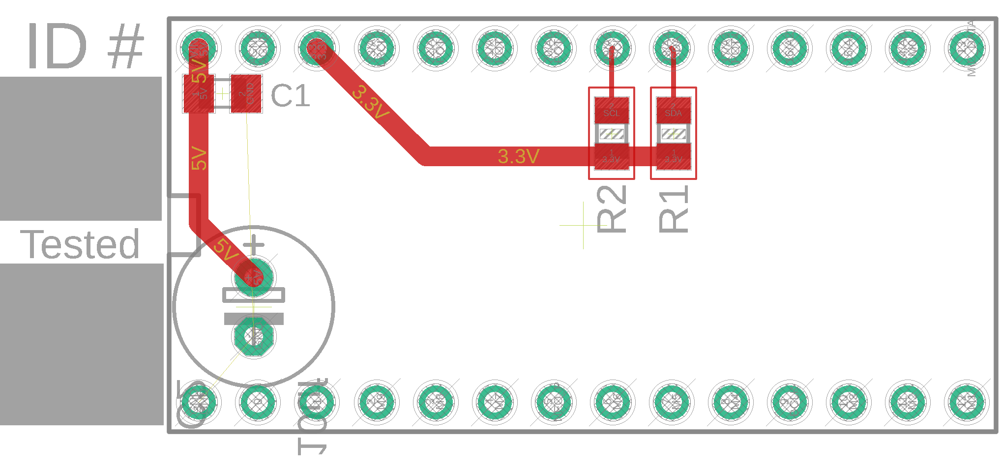
Due to its flexibility, small size, computational capability, and reasonable cost, Teensy 3.2 is the recommended microcontroller for Acropolis family genera. A benefit of incorporating the Teensy 3.2 into projects, is the microcontroller's minimal need for external passive components. Two smoothing capacitors labeled as C1 and C2 should be positioned in-between the Teensy's 5V and GND pins to most effectively stabilise power coming from the 5~V regulator. To support communication on the microcontroller's I2C bus, two 4.7~k pull-up resistors are connected between the SDA and SCL data lines and 3.3~V power (R1 and R2). These resistors are positioned close to the microcontroller's GPIO pins to simplify the design block but can be re-positioned without causing problems if needed.
Power System Design Block
Unlike the majority of the design blocks including the microcontroller, NeoPixels, and ambient light sensing blocks, the Acropolis family power system was updated, expanded, and improved through the design of Speculātor, Explorator, and Legatus. In realising these genera, the Acropolis family system recognises that the unique power requirements of each genera requires differing power sources and regulation circuitry. Therefore, the Acropolis family power system must be more flexible to accommodate different configurations in its implementation than most other design blocks. Therefore, to accommodate a broader range of artefact power requirements, the Acropolis family currently provides two power system design blocks: a lower power option that leverages the S9V11F5S6CMA regulator and a higher power option that instead uses the D24V50F5 regulator.
Low-Power Design Block
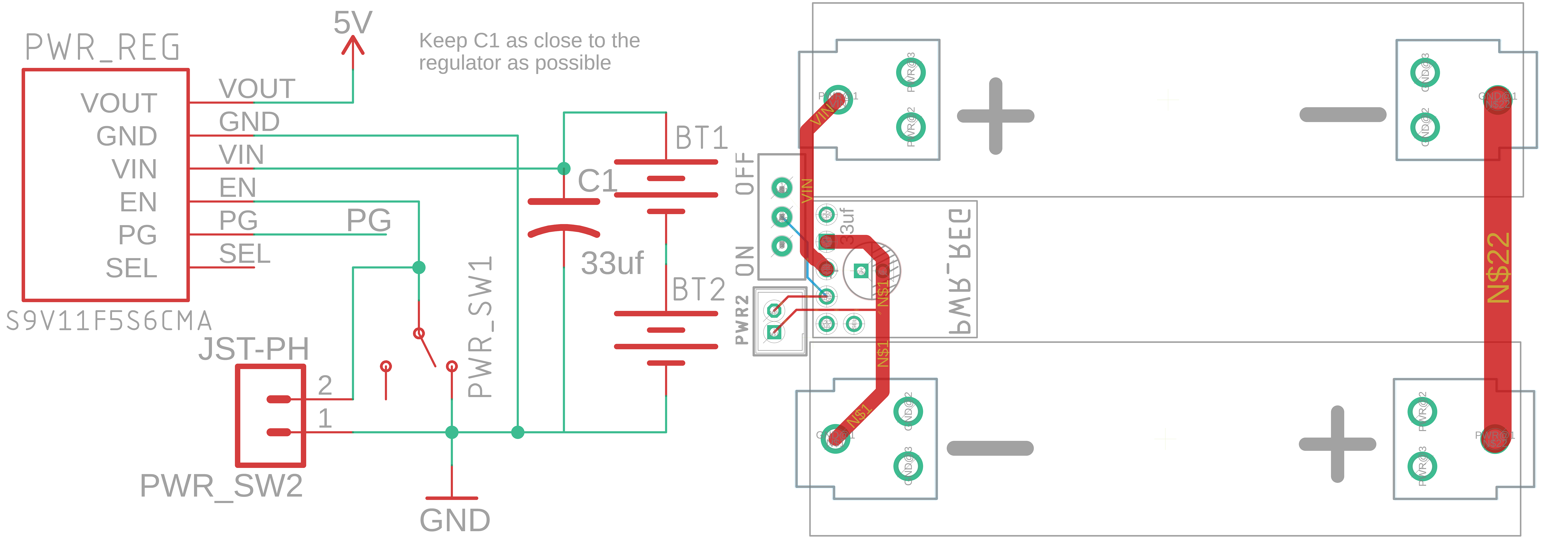
For artefacts which do not require high power on the 5 V power level, it is recommended artefacts leverage the the S9V11F5S6CMA voltage regulator. To stabilise power from the battery terminal output, the S9V11F5S6CMA voltage regulator requires C1. C1 is a 33 µF electrolytic capacitor, is connected between the positive terminal of the battery pack and the GND pin --- positioned under the regulator as can be seen in the Figure. This capacitor protects the regulator from inrush currents which can occur when batteries are connected to the power system. This capacitor should be rated for at least 20 V while its value can be increased for added protection.
To allow for regulator to be turned on and off, the design block includes a 2-pin JST-ph connector as well as an SPDT through-hole switch. Either, or both, of these footprints can be removed if not needed.
High-Power Design Block
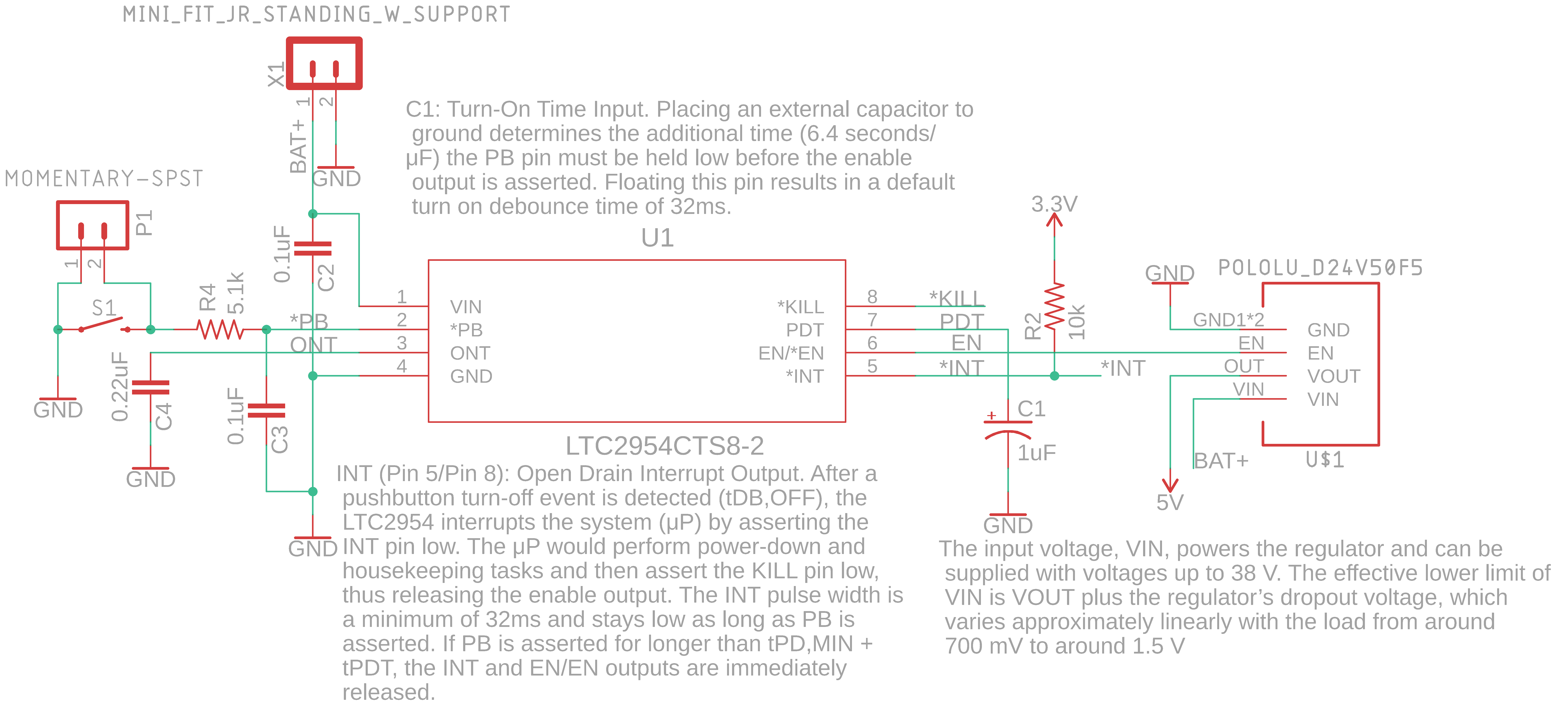
A vital implementation step for the power system design block is that the cutoff voltage threshold for the S9V11F5S6CMA must be set before any device testing. If not appropriately set, the units will either prematurely shutoff of will completely drain the batteries, causing permanent damage to the cells.
Batteries
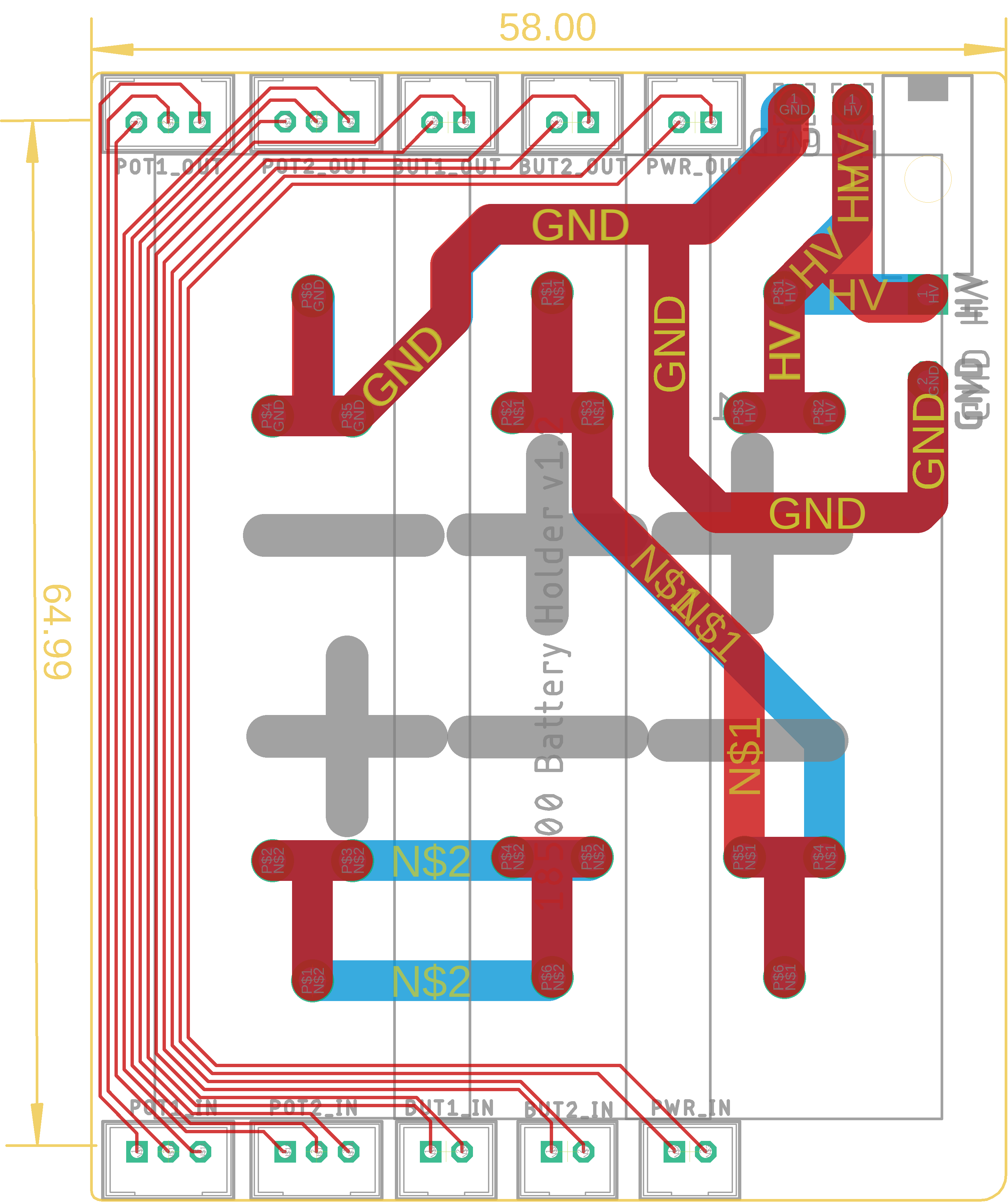
Acropolis family artefacts have levered both onboard and external battery packs. Onboard batteries provide the benefit of often reducing the overall artefact size, number of components, cost, and overall simplifies the design. Alternatively, external battery packs are safer as they are more electronically isolated, reduce the possibility of physical damage to sensitive electronic components, and allow for the battery type and number to be updated without a redesign of the mainboard PCB.
For novel Acropolis artefacts, the choose between onboard and external power should be determined by the intended use-case and design priorities of the artefact. If transportability is the primary concern and if there is high confidence in the power-system's adequacy it is recommended that onboard power is leveraged. Alternatively, if the artefact is in an earlier prototyping stage and the system's overall power requirements are unknown, external power is usually more beneficial due to its modularity.
The configuration for onboard LiPo power evolved through Speculator's iterative design process. Speculator major used BK-18650-PC4 plastic battery packs which were large, prevented positioning of individual cell, and represented a significant portion of the artefact's cost. In the interest of reducing weight, size, and cost while increasing design flexibility, these battery packs were replaced in Speculator minor's design with metal through-hole clips. In-situ testing confirmed the viability of these clips leading to their use within Explorator winder's external batter pack and Legatus major's mainboard PCB.
External batteries were leveraged with the Explorator species to ensure the genus could support a broader range of actuator power needs while supporting iteration in the physical design and electronic configuration of the genus. This allowed for Explorator chirper and Explorator chipper to leverage a 12.6~V lead acid battery and the remaining three species to use three LiPo cells connected in series without any modification to the mainboard PCB. Furthermore, this allowed for the external battery pack to be designed for the physical requirements of the particular species. For instance, Explorator chirper and Explorator chipper provided 3D printed and laser cut acrylic battery braces for their single lead-acid cell, Explorator clapper and Explorator spinner leveraged plastic packs mounted onto 3D printed braces, while Explorator winder benefited from a purpose-built battery clip PCB which also transmitted user-control data from the bottom of the board to the top.
Microphone Design Block

For Acropolis family artefacts, the MEMS microphones are I2S slave devices to the Teensy which serves as the I2S master device that generates the bit clock signal. The microphones need to maintain three connections with the Teensy, a LRCLK, BCLK, and data DIN signal.
The distance which the LRCLK, BCLK, and DIN traces can span is limited by how the I2S standard's lack of error identification functionality and its relatively high speed (between 1 and 4 MHz). This is because the I2S protocol is intended to be implemented over very short distances between two close components on a single PCB. Thus, from an electrical perspective, it is recommended that the microphones are located as close as possible to the host microcontroller. Due to the use of digital I2S MEMS microphones, the audio system is not as susceptible to EMI as an analogue system would be. Regardless, the microphone's internal mechanisms are sensitive to EMI meaning the microphone capsules should not be positioned close to components which produce strong magnetic fields.
It is vital to also take into account the acoustic implications of microphone positioning. The microphones need to be placed as close as possible to the sounds they want to hear. When possible the microphone should not sit deep inside its enclosure but instead should be as close as possible to the outside environment. When two microphones are included in a design, the two capsules should be positioned symmetrically on opposite sides of the PCB to produce the most accurate stereo field. While this just covers the basics, an extensive list of important system integration guidelines can be found in the SiSonic Design Guide.
According to Knowles, C1 and C2 need to be positioned as close to the microphone capsule as possible to maximise SNR. Of these two capacitors, C1 should be positioned the closest to the microphone. Depending on the implementation, the value of C2 might need to be decreased (as low as 20 pF), or removed altogether, if noise is observed at the microphone GND or 3.3V pads. R1, R2, and R3 are dampening resistors which must be placed as close as possible to the Teensy pins. These resistors improve signal integrity by reducing overshoots and ringing on those lines. When integrating the design block into projects, it is important to remember that to reduce EMI, the microphone should be surrounded by a ground plane. Another layout consideration is that the power and signal traces should not be routed in parallel as this could ruin cross-talk performance.